|
|
Consultancy for Recovery Based Waste Heat Power Plant
 |
What is waste heat ?
- Case 1 :Industrial process produces gases with combustible components like CO,Methane etc during manufacturing activity eg Blast furnace gas and coke oven gas in steel manufacturing process.
- Case 2 :Some times the flue gases without combustible component but at high temperatures are produced eg flue gases from sponge iron manufacturing DRI Kilns
in both cases the manufacturing industry does not have any further use of gases and heat available in them and the
gases are let out into atmosphere after burning the combustible components at the top of chimney in case 1 and
the gases are cooled in water scrubber before letting them out into atmosphere through chimney in case 2. in both cases available heat is wasted by letting out into atmosphere.
Hence this heat is called as waste heat.
ITPL proposes to use this waste heat in a boiler to generate steam at 68 bar and 490 deg C and take this superheated steam to steam turbine to generate electricity.
The generated electricity can be used for captive consumption or can be sold to grid/power trading company.
ITPL thus provides technology which converts waste heat into electricity thus making the project proponent earn rupees and increase his profits in a cases where he was wasting energy.
These waste heat based projects are also eligible for CDM benefits and by following proper procedure the project can earn CER credits which can be sold for 10 years to make additional income. |
Project description
- The purpose of the project activity is to achieve efficient use of waste heat to generate electricity. The electricity so generated shall mainly be used to meet the captive power requirement of Plant itself or sold to grid/power trading company.
- The reduction in GHG emission from facility of the project arises from the replacement / displacement of an equivalent amount of electricity to the extent of electricity generated from steam which is produced from heat recovered from waste gases, which would have been otherwise generated and supplied by coal based FBCB based captive power plant.
- The total CO2 emission reduction for the entire crediting period of 10 years have been estimated approximately 5000 tonne CO2 per MW.CDM benefits are available.
- Example for waste flue gas is a sponge iron manufacturing complex and the product is sponge iron.
Technology description: The power plant comprises of which comprises of WHRBS,Steam generated is taken to common header which also receives steam form coal based FBC and combined steam generates electricity.
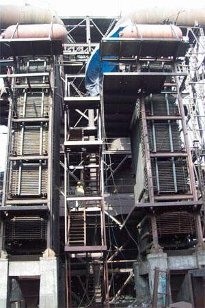
BOILERS |
Waste Heat recovery |
75 Bar and 495 deg c |
The waste heat recovery boilers are based on designs of ERK Eckrohrkessel GmbH, Germany. Technology transfer is complete. |
STEAM TURBINE GENERATOR |
Multistage, Extraction cum Condensing |
1 Number
Seam required 4 tonnes/MW@64kg/cm2a ,490 deg c |
RPM:7000
Generation voltage : 11 KV |
CONDENSOR
ESP |
Water cooled
Removes fly ash up to
100 mg/m3 |
1 number
2 numbers |
Fly ash is not generated in
The project activity. but comes with flue gases
Of ABC of DRI sponge iron kilns. |
MONITERING SYSTEM
OTHER SYSTEMS WILL
COMPRISE OF DM WATERPLANT,SILOS,
PNEUMATICCONVEYING,SYNCHRONISING SYSTEM. |
DCS, Electronic
instruments |
Steam flow,pressure,temperature
Electricity meters |
As per CDM requirement |
SUSTAINBLE DEVELOPMENT
SOCIAL BENEFITS |
1 Provides employment.
2 Enables grid to reduce the gap of 3000 MW shortage and meet its social obligation |
ECONOMICAL BENEFITS |
1 Boosts engineering sector by investing more than 400 million on in equipment purchase.
2 Enable state to earn revenues through taxes
3 Enables grid to supply electricity to other economic activities |
| ENVIRONMENTAL BENEFITS |
1 Prevents thermal pollution
2 Prevents water pollution by eliminating water scrubber.
3 Prevents fugitive pollution |
OTHER BENEFITS |
1 Fly ash given free for economical activity of brick making and cement industry |
DETAILED SCOPE OF SERVICES
Basic Engineering
Design Basis Report for:
a) Mechanical system
b) Electrical system
c) Instrumentation & control system
d) Civil, structural & architectural design
Overall plot plan
P&I diagrams for all systems
Design/specs & drg
a) Steam generator unit & its auxiliaries
Consultant will size the boiler capacity with sufficient control margin over & above the actual requirement at inlet of turbine based on “heat & mass balance diagram of TG set & also considering process stem requirement if any. Technical specification will be prepared based on the discussions & availability of fuels in the vicinity.
b) Steam turbine generator (STG)
With water cooled condenser, bleed off for feed water heater, deaerater, piping SG feed
water pump sets, HP / LP dosing systems etc. and associated auxiliaries. Consultant t
Review the technical contract
ENVIRONMENTAL IMPACTS
1. The project activity does not use any fuel. hence it does no addition to environmental pollution
2. Thermal pollution is reduced as waste heat is removed
3. Water pollution avoided as water scrubber eliminated
4. EIA study has been carried out for the entire expansion.
|
|
|